Summary
The main objective of B01 is to characterize damage by means of non-destructive testing methods. In the 1st funding period (FP), micromagnetic measurement techniques were developed to achieve this goal. The results underlined that the non-destructive characterization by means of micromagnetic analysis methods is reliable for different materials and geometries on the component surface. Furthermore, the influence of forming process parameters and of the associated forming-induced ductile damage on the fatigue behavior was determined. It was observed that forming-induced damage is spatially inhomogeneously distributed. This presents a challenge due to the fact that micromagnetic surface measurement techniques solely offer insights into the near-surface region.
Therefore, within the 2nd FP, electrical resistivity-based characterization methods were further explored to address the objective of assessing damage across the entire volume. To support these analyses, an electro-mechanically coupled computational multiscale approach was developed that allows resistivity changes to be predicted by simulations based on microscale features such as the distinct properties of individual phases, phase morphologies, and possibly microcracks and voids. A focus was laid on electrical resistance measurements of extruded 16MnCrS5 and rolled DP800 steels. A correlation between the measured electrical resistance values for different forming-induced damage states and the void volume fraction was observed, and the damage evolution during quasi-static and cyclic loading was linked to electrical resistance measurements. The conclusions drawn from the measurements were further validated through 3D nanovoid Focused Ion Beam Scanning Electron Microscope (FIB-SEM) investigations on the microscale, with the goal of developing a microstructure- and mechanism-based understanding of the process-damage-property relation. In detail, changes in the effective material response, e.g. caused by forming and fatigue loading-induced damage evolution, were predicted by resolving the microstructural information in representative unit cells. This includes the development of an electro-mechanically coupled cohesive zone formulation and the associated extension of the multiscale formulation to microstructures featuring discontinuous fields. The predictive capability of the proposed multiscale approach was demonstrated by the application to experimental data stemming from synthetically generated sample systems featuring geometrically well-defined void arrays and loading-induced microcracks. These fundamental studies contribute to an understanding of the different contributions and the various mechanisms that affect the overall resistivity of materials. Focusing on a purely macroscopic description of damage-induced electrical resistance changes and its characterization by means of experiments, the ductile damage model developed and calibrated by C02 was additionally extended to an electro-mechanical problem setting. Interpreting the resistivity as a fingerprint of the microstructure, the established modeling framework enables the separation of individual contributions such as finite geometry changes, plasticity and damage.
In conclusion, B01’s comprehensive investigations cover fast non-destructive characterization and advanced multiscale techniques. By combining experimental- and simulation-based approaches, valuable insights into electro-mechanical coupling, highly accurate measurement methodologies, and the intricate interplay of various factors that affect the accuracy of non-destructive damage characterization, are gained.
Report and current state of research
WP1: Further development and equipment extension of the sensor system (WPT)
A sensor system based on electrical resistance was developed and validated for detection of forming-induced damage. For this purpose, fully forward extruded parts of 16MnCrS5 steel with different shoulder opening angles and a constant degree of deformation were analyzed with the system. These components were selected because the microstructural properties affecting the electrical resistance are similar, while the degree of forming-induced damage in the central axis differs. The applied Keithley 2601B sourcemeter in combination with a Keithley 2182A nanovoltmeter allows the use of a delta mode, in which the polarity of the current is changed with the aim to eliminate thermoelectric effects such as the Seebeck effect. These effects are not polarity-dependent. Consequently, it was possible to isolate and demonstrate the effect of forming-induced damage via electrical resistance. The electrical resistance for components produced with 90° shoulder opening angle is reproducibly higher compared to the 30° shoulder opening angle, which has to be attributed to the higher degree of forming-induced damage, Fig. 1 [*Lüc22, *Lin22].
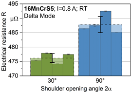
Fig. 1: Electrical resistance for parts formed with different shoulder opening angles.
Additionally, the sensor system was applied during tensile tests carried out for WP9 to non-destructively capture forming-induced damage in order to model experiments on cold-rolled DP800 steel. As external disturbances had to be eliminated, the entire tensile test system was electrically isolated. The correlation between electrical resistance and tensile loading-induced damage was demonstrated under simplifying assumptions [*Güz23b]. The extension of these studies in the 3rd FP (WP2) is aimed at quantifying the impact of relevant influencing factors on the change in electrical resistance.
WP2: Mechanism-oriented characterization of fatigue behavior of different damage conditions (WPT)
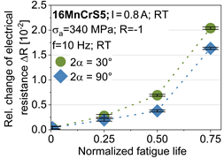
The sensor system based on electrical resistance was further adapted to the fatigue test system in order to assess fatigue loading-induced damage for 16MnCrS5 specimens. At fatigue lifetime intervals of 25%, 50%, and 75%, the specimens with different damage conditions were disassembled and subjected to analyses using the electrical resistance measurement setup. Illustrated in Fig. 2 are exemplary outcomes for specimens formed with 30° and 90° shoulder opening angle. For the purpose of comparison, changes in electrical resistance are presented using absolute values (Fig. 2a) and relative values referring to the initial values at the start of the test (Fig. 2b). The dispersion bands accompanying each measurement point illustrate the temperature-dependent scattering occurring over 10 minutes measurement periods. Up to 50% fatigue lifetime, the relative change in electrical resistance ΔR increases with small rates for both shoulder opening angle configurations. Nevertheless, the increase during the transition from 25% to 50% of fatigue life is more pronounced for the 30° specimen, which experienced comparatively less forming-induced damage. A notable change in electrical resistance takes place between the 50% and 75% lifetime stages, ending at 2.0% for the 30° configuration and 1.6% for the 90° configuration. Within this range, the electrical resistance increase is similar for both orientations. Failure becomes evident when a predetermined cumulative damage threshold is reached. This cumulative damage encompasses damage from forming-induced damage as well as fatigue-induced damage. Consequently, the 30° specimen with lower initial forming-induced damage is able to endure greater levels of fatigue damage compared to its 90° counterpart. Hence, a clear mechanism-oriented correlation bet-ween electrical resistance variations and fatigue-induced degradation is also demonstrable in this context [*Lüc22, *Lin22]. Experimental findings show that microcracks, dislocations, voids and geometry influence the electrical resistance [Bis22, Cor16]. However, the quantitative contribution of these relevant factors to the electrical resistance is still unknown but necessary for the determination of forming- and fatigue loading-induced damage within TRR 188 and therefore an important research question of the 3rd FP (WP2).
 |
|
|
Fig. 2: Electrical resistance increase as a) absolute values and b) relative values referring to the initial values at the start of the test due to the fatigue loading-induced damage over normalized fatigue life for shoulder opening angles of 30° and 90°. |
In addition to characteristic cyclic softening during fatigue loading, cyclic creep effects were detected. Therefore, a consistent reduction in the total mean strain due to fatigue loading with a stress ratio R = 1 (fully‑reversed loading, tension-compression) was observed for 16MnCrS5 specimens. The significant reduction up to a total mean strain of -0.32% resulted in a max. total strain that turned negative. Digital Image Correlation (DIC) tests were performed so as to exclude influencing factors due to slipping of the extensometer, torsional effects, or specimen buckling. Cyclic creep effects are well known at stress ratios 0 < R < 1, resulting in a shift of the total mean strain. The underlying cause of the observed negative cyclic creep effects are expected to be attributed to the Bauschinger effect, stemming from the significant plastic deformation endured during the forming process. In order to determine the influence of forming-induced damage on this phenomenon, further investigations over a range of mean stresses are required in the 3rd FP (WP3), considering forming load paths.
WP3: Intermitted microstructure characterization (WPT)
To determine the effect of forming-induced damage on the electrical resistance, comprehensive microstruc-ture analyses were undertaken. In the Scanning Electron Microscope (SEM) studies of 16MnCrS5 steel, a difference in the number of voids on the central axis of the forward rod extruded parts with shoulder open-ing angles of 30° and 90° was observed. A higher concentration of voids is observable for the 90° shoulder opening angle configuration as expected. The microstructural attributes of the formed components at 30° and 90° angles exhibit a comparable nature and the average grain size measures 10.0 ± 0.5 μm. The forming process has resulted in a reduction of the grain size by half, with both conditions yielding a hardness of 190 ± 5 HV1 when the cross-section is examined. These results were also supported by other projects by means of density measurements (A02) as well as by the panoramic detection of the void area in the SEM (B04). Further Electron Backscatter Diffraction (EBSD) analyses revealed a grain elongation and anisotropic alignment with the direction of material flow during forming for both conditions compared to the initial state. These investigations affirm that the higher electrical resistance values of the more forming-induced dam-aged specimen with 90° in Fig. 1 can be explained by the different void volume and dislocation densities exclusively, as the other microstructure characteristics mentioned are similar for both configurations [*Lüc22, *Lüc23]. The results of the intermittent characterizations are described in combination with the fa-tigue properties in WP4.
WP4: Mechanism-based correlation of microstructure with fatigue properties (WPT)
The fatigue specimens of 16MnCrS5 were examined within this work package in order to establish a correlation between fatigue loading-induced microstructural changes and electrical resistance. Selected samples have been extensively analyzed using FIB-SEM based on ECCI and STEM studies. In Fig. 3a, an ECCI image of a specimen formed with a shoulder opening angle of 30°, having reached 75% of its lifetime, is presented. The contrast on the image is created by the different orientations of the subgrains. This method is beneficial for visualizing dislocations. An enlargement is displayed in Fig. 3b, where dislocations are most noticeable at the edges of dark subgrain boundaries, visible as white areas. Currently, an assessment of the dislocation density can only be made qualitatively. Both images reveal numerous nanoscale voids that are not commonly found near manganese sulfides, but rather randomly distributed, predominantly between cementite lamellae. In comparison to the cyclically undamaged specimen, a significant increase of the numbers of voids is evident, which aligns with the findings from the 3D void volume investigations. The presence of nanovoids raises the question of how this forming-induced damage influences the fatigue strength at higher strain rates, smaller load amplitudes, and higher number of cycles to failure. It is well known that fatigue cracks in the low-cycle fatigue (LCF) and high-cycle fatigue (HCF) ranges are mostly initiated at the surface, while volume defects inside the specimens initiate fractures in the VHCF regime. These analyses will be extended in the 3rd FP (WP2) to systematically acquire images for multiple fatigue states and contribute qualitatively to the evaluation of void number and dislocation density.
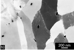

Fig. 3: a) Electron Channelling Contrast Imaging (ECCI) overview micrograph and b) close‑up micrograph with voids and dislocations of a specimen with shoulder opening angle of 30° that reached 75% lifetime.
WP5: Development of a lifetime prediction based on resistometry measurements (WPT and IM)
As most of the results of the 2nd FP will be combined in this WP, the main work is planned for the last year of the 2nd FP. So far, a correlation between the increase in electrical resistance after 50% of the lifetime and the remaining lifetime is being used for the lifetime prediction. Further experiments are currently being conducted to complete the assessment and finalize the fatigue prediction by the end of the current FP.
WP6: Development of an electro-mechanical multiscale approach (IM)
In the 2nd FP, a multiscale simulation approach for electrical conductors was developed and implemented in order to support non-destructive testing methods [*Kai21a]. The governing set of electro-mechanical field equations was derived, establishing a basis for the computational multiscale formulation. Based on these developments, the framework was extended to a continuum with interfaces at the microscale so as to address the effect of material interfaces, such as microcracks or grain and phase boundaries, on the effective material properties [*Güz23c]. For this purpose, cohesive-type interfaces were considered at the microscale such that displacement and electric potential jumps were accounted for. In order to investigate deformation-induced property changes at the microscale, interface decohesion was exemplarily studied.
The investigation of microscale images reveals that dual phase steels exhibit heterogenous microstructures. As illustrated in Fig. 4, DP800 steels consist of martensite islands that are embedded in a ferrite matrix with both phases showing an entirely different material response. Furthermore, voids of various sizes and morphologies as well as phase and grain boundaries occur. The developed framework is capable of modeling these different microscale heterogeneities. The corresponding effective conductivity tensors can be obtained from the unit cell problem (by using for instance finite element-based techniques) to study the effect of the underlying microstructure. Specifically speaking, different void [*Kai21a] and material interface [*Güz23c] geometries were analyzed and effective stiffness and electrical conductivity tensors were calculated. The simulation results show that the effective material response is significantly affected by the underlying microstructure and enable a systematic study of the influence of the different microscale features depicted in Fig. 5. To demonstrate the capabilities of the computational multiscale approach for continua featuring material interfaces, an electro-mechanically coupled inclusion debonding problem was, amongst others, studied. The corresponding simulation results shown in Fig. 4 clearly exemplify the influence of mechanically-induced interfacial degradation processes on the effective electrical conductivity.
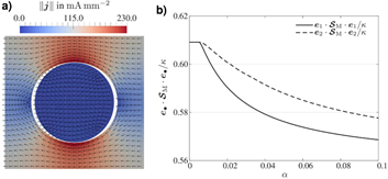
Fig. 4: a) Electric current density field for a matrix-inclusion problem and b) change in the macroscopic conductivity tensor due to the decohesion of the matrix-inclusion interface with increasing loading-parameter , [*Güz23c].
Eventually, the proposed small strain framework [*Kai21a] was extended to a finite deformation setting [Kai21b]. Various representative 2D and 3D boundary value problems were selected to study the influence of finite geometry changes at the microscale on the effective electrical conductivity tensor at the macroscale. Additionally, a biaxial tensile test specimen with microstructures containing circular voids was analyzed in a “true multiscale setting” to study the effect of mechanically-induced microscale processes on macroscale experiments.
The fundamental simulation-based developments presented in this WP contribute to an understanding of the influence of the microstructure on the effective material properties at the macroscale. Combining the electro-mechanical multiscale approach with experimental resistance measurements (WP8) makes it possible to study the various mechanisms (WP7) that affect the overall conductivity of materials.
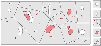
Fig. 5: Sketch of a representative SEM panorama image of DP800 steel that contains voids, cracks, inclusions, secondary phases and grain boundaries (left) with exemplary representative volume elements (right).
WP7: Development of electro-mechanical cohesive zone formulations for electrical conductors (IM)
This WP focuses on the development and implementation of an electro-mechanically coupled cohesive zone formulation for electrical conductors. The cohesive zone model, established in the 1960s, is commonly used to analyze and simulate the behavior of material interfaces. Coupled with finite element formulations, cohesive zone formulations are particularly useful in addressing problems related to failure processes along an interface, such as debonding or delamination, and for describing the specific properties of zero-thickness material interfaces. The importance of these microscale features and processes is exemplified by the TRR 188 studies on phase boundaries, grain boundaries, voids and microcracks shown in Fig. 6.
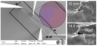
Fig. 6: Study of distinct microscale features such as grain boundaries (courtesy of Hanna Bishara) and voids (courtesy of B04).
Based on experimental findings suggesting changes in electrical properties due to deformation-induced microcracks, an electro-mechanically coupled cohesive zone formulation that incorporates the evolution of interface damage was proposed [Kai21c]. The developed finite element implementation was validated by an analytical solution and representative 2D boundary value problems focusing on intergranular crack propagation were studied, Fig. 7. Particular focus was laid on the evolution of interface damage and its influence on the electrical conductivity. The representative examples were of academic nature, and the models are not calibrated to TRR 188 materials at this stage. This motivates the combined experimental-simulation-based work in WP6 of the 3rd FP.
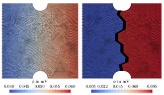
Fig. 7: Intergranular crack propagation along grain boundaries and electric potential field during damage evolution, [Kai21c].
The thermodynamically consistent framework was further extended to thermo-electro-mechanically coupled problems in 3D settings [*Güz23a]. An analytical solution was derived for validation purposes and thermo-electro-mechanically-induced interface failure processes were studied. The framework serves as a basis for future developments in the 3rd FP (WP5, WP6) so as to gain a comprehensive understanding of microscale processes and accurately predict the electro-mechanical interactions at the microscale.
WP8: Calibration of developed microscale models (IM)
WP8 addresses the calibration and verification of the proposed multiscale approach based on experiments. To achieve this objective, three studies were conducted in a close collaboration with B03. The first study focuses on the influence of microcracks on effective macroscopic electrical and mechanical material properties [*Kai21d]. For this purpose, thin metal films under cyclic (mechanical) loading were investigated by in-situ confocal laser scanning microscopy (CLSM) and four-point probe measurements were performed. Representative volume elements (RVEs) with microcracks were generated by digitization of micrographs and the corresponding conductivity tensors were obtained. A comparison of experimental findings and simulation results indicates a good agreement and demonstrates the applicability of the multiscale approach to non-destructive testing methods. In the second study [Kai23], microstructures were generated by FIB milling to obtain artificial voids. The electric potential change was measured by a four-point probe technique. Various RVEs with well-defined void morphologies were analyzed to study the changes in electrical resistivity due to microscale voids. The experimental and simulation-based curves in Fig. 8 show the good agreement between experimental findings and simulation-based predictions. In the (ongoing) third study, laminate-like pearlite structures are investigated. Experimental measurements carried out by B03 in cooperation with the TRR 188‑supported visits of Dr. Hanna Bishara from Tel Aviv University reveal the different material properties of ferrite and cementite. Three-dimensional RVEs with ferrite and cementite phases are generated based on the experimentally recorded data and the predicted electrical conductivity tensors are compared with the experimental findings. The various investigations clearly show that the approach proposed in WP6 has the potential to contribute to an understanding of the different mechanisms that affect the overall conductivity of materials and to eventually support the development of non-destructive testing methods. The computational multiscale approach was validated in the 2nd FP by a systematic study of 2D and 3D model problems. Based on these developments, the calibration of tailored microscale models is in the focus of WP6 in the 3rd FP.
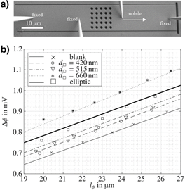
Fig. 8: a) Experimental setup for four-point probe measurements and b) comparison of electric potential difference as a function of the distance between the inner two needles for artificially created microstructures (experiments: markers (B03), simulations: lines (B01)), [Kai23].
WP9: Macroscale simulations and calibration of the proposed approach (IM and WPT)
Experimental findings show that various mechanisms, such as the formation of microcracks [Cor16], and the accumulation of dislocations [Bis22], influence the electrical conductivity as schematically shown in Fig. 9. In order to support the non-destructive electrical characterization of damage, these mechanisms need to be accounted for in simulations. This WP focuses on macroscopic, single scale simulations of DP800 steel. For this purpose, the ductile damage model developed and calibrated by C02 [Spr20] was extended to electro-mechanical coupling [*Güz23b]. The model serves as a basis for the characterization of damage in ductile materials through electrical resistance measurements. A typical gradient-enhanced ductile damage formulation was used and the governing equations for continua under combined electro-mechanical loadings were derived. The mechanical subproblem results in the local form of the balance equation of linear momentum and the micromorphic balance relation, while the electrical subproblem is governed by the continuity equation for the electric charge. By assuming that the electrical conductivity is a function of damage and plasticity, the proposed framework aims at separating these distinct contributions. The particular form of the degradation function and the occurring model parameters are to be based on experiments. Against this background, tensile tests were performed on flat DP800 steel specimens in the micro tensile test machine shown in Fig. 9 and the electrical resistance was continuously measured. As sketched in Fig. 9, the effect of damage can be separated from the influence of plasticity by proper heat treatment of the samples so as to obtain a microstructure with a significantly reduced number of dislocations. The influence of the finite geometry change is intrinsically accounted for in the extended C02 model and was experimentally recorded using DIC measurements.
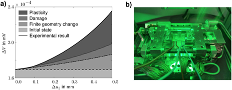
Fig. 9: a) Expected (microstructural) contributions to the overall change in the measured electric potential difference under tensile loadings and an applied constant current, shown as measured change in voltage ΔV with respect to applied transverse displacement , [*Güz23b], and b) micro tensile test machine with a nanovoltmeter for resistance measurements.
Understanding how separate mechanisms contribute to the overall resistivity is a challenging task since these typically occur simultaneously. Against this background, a simplified modeling approach is additionally considered (ongoing work). The exact geometry of the deformed specimens is taken into account by making use of high-resolution scanning technique, such as light microscopy imaging or 3D scanning. By digitalizing the deformed samples, changes in electrical resistance due to changes in geometry are incorporated in the model. Comparing the experimental results of the heat-treated samples and the electrical simulation-based predictions for the exact sample geometries is expected to reveal the effect of damage on the electrical resistance measurements. These studies are continued in the 3rd FP with particular focus lying on the intrinsic anisotropy of damage (WP8) and on the quantification of influencing factors such as dislocation densities, microcracks and voids considering forming- and fatigue loadings (WP2, WP7).
Conclusion and derived research questions
During the 2nd FP, it was shown in the experimental part that electrical resistance correlates with both forming- and fatigue loading-induced damage and is therefore well suitable for non-destructive characterization. However, as there are many factors that influence electrical resistance, it has not yet been possible to fully quantify the effect of damage. In the simulation part, an electro-mechanical multiscale approach was developed to support the non-destructive characterization efforts. The proposed modeling approach makes it possible to account for various microstructural features such as voids, inclusions, microcracks, and material interfaces with particular focus lying on their effect on the electrical resistance. This was demonstrated by various combined experimental-simulation-based investigations that clearly show the applicability and potential of the established framework. For the implementation of the non‑destructive measurement technique in the production processes considered in project area A, the quantification of microstructure-induced changes in the electrical resistance due to forming- and fatigue loading-induced damage is the main research question of the 3rd FP.
Project- and subject-related list of publications
[*Baa21] Baak, N.; Hajavifard, R.; Lücker, L.; Rozo Vasquez, J.; Strodick, S.; Teschke, M.; Walther, F.: Micromagnetic approaches for microstructure analysis and capability assessment. Materials Characterization 178, 111189 (2021) 1–14. DOI: 10.1016/j.matchar.2021.111189
[Ber19] Berthelsen, R.; Menzel, A.: Computational homogenisation for thermo-viscoplastic composites: Large strain formulation and weak micro-periodicity. Computer Methods in Applied Mechanics and Engineering 348 (2019) 575–603. DOI: 10.1016/j.cma.2018.12.032
[Bis20] Bishara, H.; Ghidelli, M.; Dehm, G.: Approaches to measure the resistivity of grain boundaries in metals with high sensitivity and spatial resolution: A case study employing Cu. ACS Applied Electronic Materials 2 (2020) 2049−2056. DOI: 10.1021/acsaelm.0c00311
[Bis22] Bishara, H.; Tsybenko, H.; Nandy, S.; Muhammad, Q.K.; Frömling, T.; Fang, X.; Best, J.P.; Dehm, G.: Dislocation-enhanced electrical conductivity in rutile Ti02 accessed by room-temperature nanoindentation. Scripta Materialia 212, 114543 (2022) 1–5.
DOI: 10.1016/j.scriptamat.2022.114543
[Cor16] Cordill, M. J.; Glushko, O.; Putz, B.: Electro-mechanical testing of conductive materials used in flexible electronics. Frontiers in Materials 3, 11 (2016) 1–11. DOI: 10.3389/fmats.2016.00011
[*Güz23a] Güzel, D.; Kaiser, T.; Menzel, A.: A thermo-electro-mechanically coupled cohesive zone formulation for predicting interfacial damage. European Journal of Mechanics A/Solids 99, 104935 (2023) 1–13. DOI: 10.1016/j.euromechsol.2023.104935
[*Güz23b] Güzel, D.; Kaiser, T.; Lücker, L.; Baak, N.; Walther, F.; Menzel, A.: Characterisation of damage by means of electrical measurements: numerical predictions. Procedia of Applied Mathematics and Mechanics 23, 2, e202300013 (2023) 1–8. DOI: 10.1002/pamm.202300013
[*Güz23c] Güzel, D.; Kaiser, T.; Menzel, A.: A computational multiscale approach towards the modelling of microstructures with material interfaces in electrical conductors. Mathematics and Mechanics of Solids (2023) 1–20. DOI: 10.1177/10812865231202721
[*Lin22] Lingnau, L. A.; Lücker, L.; Walther, F.: Resistometriebasierte Charakterisierung der umform- und ermüdungsinduzierten Schädigung im Einsatzstahl 16MnCrS5. Werkstoffprüfung 2022 - Werkstoffe und Bauteile auf dem Prüfstand, ISBN 978-3-88355-430-3 (2022) 406–411.
[*Lüc22] Lücker, L.; Lingnau, L. A.; Walther, F.: Non-destructive direct current potential drop assessment of forming-induced pre-damage in AISI 5115 steel. Procedia Structural Integrity 42 (2022) 368–373. DOI: 10.1016/j.prostr.2022.12.046
[*Lüc23] Lücker, L.; Walther, F.: Direct current potential drop characterization of forming-induced pre-damage influence on bending fatigue behavior of 16MnCrS5. Procedia Structural Integrity 46 (2023) 94–98. DOI: 10.1016/j.prostr.2023.06.016
[*Kai21a] Kaiser, T.; Menzel, A.: An electro-mechanically coupled computational multiscale formulation for electrical conductors. Archive of Applied Mechanics 91 (2021) 1509–1526. DOI: 10.1007/s00419-020-01837-6
[Kai21b] Kaiser, T.; Menzel, A.: A finite deformation electro-mechanically coupled computational multiscale formulation for electrical conductors. Acta Mechanica 232 (2021) 3939–3956. DOI: 10.1007/ s00707-021-03005-5
[Kai21c] Kaiser, T.; Menzel, A.: Fundamentals of electro-mechanically coupled cohesive zone formulations for electrical conductors. Computational Mechanics 68, 1 (2021) 51–67. DOI: 10.1007/s00466-021-02019-z
[*Kai21d] Kaiser, T.; Cordill, M. J.; Kirchlechner, C.; Menzel, A.: Electrical and mechanical behaviour of metal thin films. International Journal of Fracture 231 (2021) 223–242, DOI: 10.1007/s10704-021-00582-3
[*Kai23] Kaiser, T.; Dehm, G.; Kirchlechner, C.; Menzel, A.; Bishara, H.: Probing porosity in metals by electrical conductivity: Nanoscale experiments and multiscale simulations. European Journal of Mechanics A/Solids, 97, 104777 (2023) 1–9. DOI: 10.1016/j.euromechsol.2022.104777
[Ott23] Otto, J. L.; Sauer, M. L.; Brink. M.; Schaum, T.; Lingnau, L. A.; Macias Barrientos, M.; Walther, F.: A 2D and 3D segmentation-based microstructure study on the role of brittle phases in diffusion brazed AISI 304L/NiCrSiFeMoB joints. Materials & Design 235, 112401 (2023) 1–10. DOI: 10.1016/ j.matdes.2023.112401
[Spr20] Sprave, L.; Menzel, A.: A large strain gradient-enhanced ductile damage model: Finite element formulation, experiment and parameter identification. Acta Mechanica 231, 12 (2020) 5159–5192. DOI: 10.1007/s00707-020-02786-5
[Spr23] Sprave, L.; Menzel, A.: A large strain anisotropic ductile damage model – On effective driving forces and gradient-enhancement of damage vs. plasticity. Computer Methods in Applied Mechanics and Engineering 416, 116284 (2023) 1–34. DOI: 10.1016/j.cma.2023.116284
[Tem11] Temizer, I.; Wriggers, P.: Homogenization in thermoelasticity. Journal of Mechanics and Physics of Solids 59, 2 (2011) 344–372. DOI: 10.1016/j.jmps.2010.10.004