Summary
In the first two funding periods, a broad knowledge of damage evolution in cold forging at large plastic strains has been acquired for the case-hardening steel 16MnCrS5. For the processes of rod extrusion, hollow extrusion, can extrusion, ironing and upsetting, the effect of process parameters on the load path¹ and the resulting damage was studied. To determine the relationship between load path and damage evolution, stress states were systematically prescribed in experiments to investigate the effects of triaxiality and Lode parameter carefully isolated from each other. It was found that high stress triaxialities and plane strain states (Lode parameter L = 0) result in high damage evolution. Multi-step forming experiments have shown that the accumulated damage in a first process step has an effect on the damage evolution in a subsequent step. For instance, upsetting conditions in a first step result in decohesion of inclusions from the matrix, which will then enlarge under hydrostatic tension in a second step.
¹Load path: The history of hydrostatic stress (described by stress triaxiality) and deviatoric stress (described by Lode parameter) of a material point passing through the forming zone
The observed dependencies between load path and damage evolution have been translated into a simple model that can be applied as a post-processing tool to FEM simulations to give realistic predictions of void area fractions for forming sequences with various load paths. This tool allows to design damage-controlled cold forging process routes, and accordingly produce parts with increased product performance. It was demonstrated that fatigue strength, impact toughness and elastic stiffness can be increased by reducing damage during forming by choosing process parameters accordingly or modifying processes, e.g. by adding counter pressure.
Beside the effect of forming on damage evolution, also the effect of heat treatment between forming stages or at the end of the forming process sequence was investigated. It was shown that the forming-induced damage is significantly reduced by recrystallization. Consequently, damage-controlled forming needs to be especially considered in process steps that are not followed by a heat treatment above recrystallization temperature, such as annealing or hardening.
A complex cold forged demonstrator part was manufactured by different sequences of backward can extrusion, forward hollow extrusion and ironing. It was shown that it is possible to design a process route with significantly reduced damage, without affecting the geometry and strain hardening distribution of the final product. The impact energy absorption in Charpy tests of the formed demonstrator was increased by 30%. This demonstrates that the performance of complex products can be increased by damage controlled forming.
The first goal of the 3rd funding period is to explore the effect of closed and potentially healed voids on product performance. It was observed in multi-stage processes, that voids which are induced in a first forming step can subsequently be closed in a second forming operation if the hydrostatic pressure is large enough. However, it is not known yet, if voids only decrease in size (shrinkage) and finally reduce to zero volume (closure) or if bonding and dissolution of the internal void interfaces takes place (healing). To study this phenomenon, material will be cold extruded under controlled stress states to firstly trigger void growth and secondly close these voids. The closed and potentially healed voids are surveyed in TEM-investigations by project B04 to understand the ongoing effects at microscale. To examine the macroscopic effect on product performance, the impact toughness of the extrudates is determined by Charpy tests. In order to examine if the performance of a material can be restored by void closure/healing, the extrudates are compared to material that has not undergone void closure.
The second goal is to not only increase nominal product performance values, but also increase the reliability of cold forged parts. Due to batch fluctuations in material properties, damage evolution in cold forging is not deterministic. However, using methods of uncertainty quantification in collaboration with project C06, damage control can be performed under consideration of such variabilities, with the aim of producing more reliable products. To effectively obtain data for probabilistic mathematical models that can describe the occurring variability, large number (50 specimen) of Charpy tests on extruded parts are carried out. Experiments with and without active control of damage will give information on interaction between the amount of damage and its variability. The obtained probabilistic mathematical models are put to the test and are applied to a cold forged demonstrator part.
This demonstrator part will bring the comprehensive knowledge on damage evolution in cold forging to application. To this end, a pressure vessel as used in e.g. airbag gas generators is manufactured in close cooperation with project A09. Based on the demonstrator parts produced in the 2nd funding period, damage-controlled process sequences are designed to manufacture parts with different damage levels, made from case hardening steel 16MnCrS5, according to geometric specifications given by A09. With the help of scanning electron microscopy (SEM) measurements and the damage models developed within the TRR, realistic damage distributions of the manufactured parts are passed to A09 as an input for the performance assessment in terms of pressurization tests of the cold forged vessels.
All investigations in this project have exclusively been conducted so far only for the cold-forging steel 16MnCrS5. As 80% of these steel components are heat treated above recrystallization temperature and it has been found for this material that damage is significantly reduced during heat treatment, in the 3rd funding period materials that are not heat treated after forming will be investigated: An aluminum alloy (AA6082) where damage occurs at hard precipitates as well as an austenitic stainless steel (1.4301) that is increasingly used in forging of components to save the heat treatment energy. The methods of damage analysis and control developed in the 2nd funding period for forward rod and forward hollow extrusion allow to control hydrostatic and deviatoric conditions at large plastic strain and to extract specimens for assessment of the product performance. Due to the different microstructure of AA6082 compared to 16MnCrS5, also different damage mechanisms are expected and will be characterized in cooperation with project area B. Austenitic steels are typically warm forged, as they show severe work hardening at room temperature. Thus the effect of warm forging on damage evolution in 1.4301 is investigated. The material shows a distinct plateau in flow stress in the temperature range of 200°C to 380°C. It is expected that increased temperatures decrease the phase hardness differential and thus reduce damage evolution. The effect of strain induced martensite formation in austenitic stainless steels takes place at lower temperatures [Wei06] and is intentionally excluded in the investigations.
Report and current state of research
In the 2nd funding period, damage control in cold forging was extended to complex process sequences, including multiple process variants and heat treatments. The effect of deviatoric stress is shown isolated from the influence of hydrostatic stress in a simple experiment for the first time in literature. An increased damage evolution at constant plastic strain and triaxiality is found for a Lode parameter L = 0, representing plane strain, as compared to L = -1. Systematically changing load paths in two-stage experiments shows a distinct dependence of damage evolution on pre-damage from previous forming stages. To describe these effects in complex cold forging sequences an uncoupled model is proposed. In the next paragraphs selected results about the effect of load path changes, heat treatment, process parameters and process sequences on damage will be presented.
Effect of Load Path Changes on Damage (WP 1)
Complex cold forged parts are often manufactured by a sequence of different process variants. Thus, abrupt changes in load path may occur. So far, damage evolution in cold forging has only been studied under monotonic load cases. To investigate load path changes at large plastic strains, sequences of extrusion (deviatoric uniaxial tension) followed by upsetting (deviatoric uniaxial compression), Route A, and vice versa, Route B, are considered. For Route B, a billet is compressed to a global plastic strain of εp = 0.3 and subsequently forward rod extruded with an extrusion strain of εp = 0.3, resulting in a total equivalent plastic strain of εp = 0.6. As a cylindrical billet is needed for the extrusion step, the upsetting is conducted in a cylindrical die to counteract the bulging. Simulations using the commercial FE-code Abaqus show large areas of homogeneous plastic strain along the central axis (Fig. 1a), which allows to obtain statistically relevant large-area SEM-measurements. Evaluation of the load path shows an increase in triaxiality during extrusion for the pre-strained specimen (Fig. 1b). This is explained by the decreased work hardening rate of the material after pre-straining, which results in a lower hardness gradient in the forming zone and thus higher stress triaxialities [Her20].
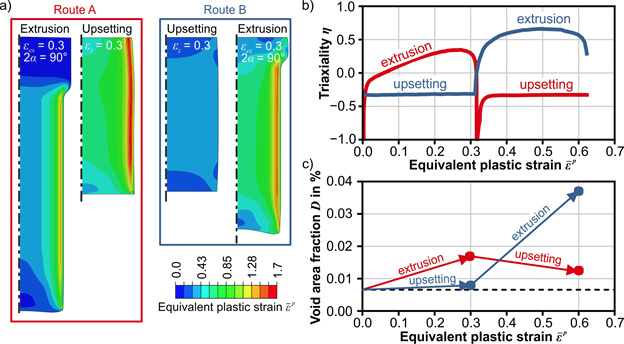 |
| Fig. 1: a) Equivalent plastic strain distribution in extrusion-upsetting (Route A) and upsetting-extrusion-experiments (Route B), b) corresponding triaxiality histories, evaluated on the central axis and c) observed void area fractions (SEM-measurements). |
SEM-investigations show that load path changes can have a strong effect on damage evolution. The void area slightly increases during upsetting of the initial material (Route B), whereas it decreases in upsetting of the extruded material (Route A), even though the stress state and strain increment are identical for both process steps (Fig. 1c). This phenomenon is explained by different damage mechanisms being triggered dependent on the damage state before forming. In upsetting of the initial material (Route B), new voids nucleate primarily by decohesion of MnS inclusions from the matrix material (Fig. 2a). In contrast, during upsetting of the extruded material (Route A), a large number of voids in terms of cracked MnS inclusions is present. These voids are likely to shrink due to hydrostatic pressure during upsetting, resulting in a decreased void area fraction.
A load-path-dependent damage evolution becomes also evident during extrusion of pre-strained material. The decohesion during previous upsetting results in further separation of matrix and inclusion due to the hydrostatic tension present in extrusion (Fig. 2b). Paired with the typical inclusion cracking in extrusion under positive triaxialities, this leads to an accelerated increase in void area fraction compared to extrusion of the initial material, where primarily only inclusion cracking takes place. Similar effects can be observed by 3D X-ray imaging of an aluminum alloy in shear with subsequent tensile loading [Kon22]. The accelerated damage evolution after compression to tension loads, can also be observed by decreased fracture strains [Zis22].
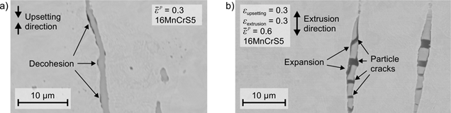 |
| Fig. 2: Damage mechanisms in route B: a) Void nucleation by particle-matrix-decohesion in upsetting test and b) accelerated void growth in subsequent forward rod extrusion due to expansion of debonded areas. |
Effect of Deviatoric Stresses on Damage (WP 1, WP 3)
The isolated effect of hydrostatic stress on damage evolution was shown in the 1st funding period by investigations on the central axis of forward extruded rods. The Lode angle was kept constant to L = -1 in these investigations. Studies of fracture loci [Bai08] or theoretical frameworks and unit-cell simulations [Bar07] show a Lode parameter dependency. However, the isolated Lode parameter-effect on damage mechanisms and evolution was not studied yet experimentally. Adjusting only the deviatoric stress is challenging, as most experiments do not allow setting specific Lode parameters without affecting triaxiality at the same time. This can be overcome by actively controlling triaxiality in extrusion experiments by application of counterpressure.
To show the effect of deviatoric stress on damage for constant hydrostatic stress and constant plastic strain, forward rod extrusion and forward hollow extrusion experiments can be used. In rod extrusion, a cylindrical billet is pushed through a conical die (Fig. 3a). The rotational symmetry results in a Lode parameter of L = -1 on the central axis. In hollow extrusion, a tubular billet is supported by a mandrel, constraining the inner circumference of the work piece to a given value. Thus, the strain component in tangential direction vanishes on the inner circumference. The resulting plane strain state yields a Lode parameter of L = 0 (Fig. 3b). However, also the triaxiality during forming varies between these processes. Thus, counterpressure is applied during rod extrusion, to reduce the triaxiality to the same value present in hollow extrusion (Fig. 3c). The extrudate diameters can be set such that in each process the same local plastic strains of εp = 0.33 and εp = 0.5 are obtained. For each strain level, damage is quantified in the rod- as well as in the hollow extrudate by SEM and density measurements. All measurements confirm increased damage evolution for a Lode parameter of L = 0 (Fig. 4).
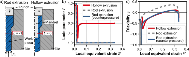 |
| Fig. 3: a) Experimental setup to compare different deviatoric stress separated from effects of hydrostatic stress and plastic strain, b) corresponding Lode parameter and c) triaxiality. |
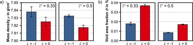 |
| Fig. 4: Damage quantification of material extruded under different Lode parameters. Both, density measurements (a) and SEM-measurements (b) show an increased damage evolution for L = 0. |
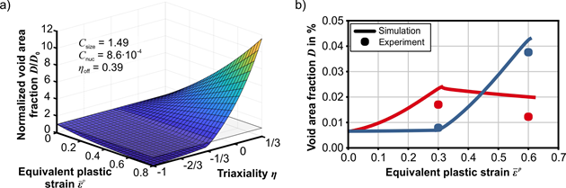
Modelling Void Area Fraction Evolution under Complex Load Paths (additional work)
The observed effects of void closure and load path dependent damage evolution are rarely considered in existing ductile damage models. Thus, a simple evolution equation is proposed to give predictions of void area fractions based on load paths extracted from elastoplastic simulations [*Git23b]. The effect of damage on flow stress is negligible in cold forging operations [*Git23a]. Thus, modelling plasticity uncoupled from damage is reasonable and allows for less time consuming simulation of complex cold forging routes.
The evolution law for damage is split into a void nucleation term fnuc(η) and a void size term fsize(η), which describes growth as well as shrinkage. With the initial void area fraction D0, the damage evolution law reads:
![]()
The size term is given by a modified version of the works of Rice and Tracey [Ric69]:
![]()
where Csize represents a material specific parameter. Depending on the triaxiality η, the size term can become negative. Positive triaxialities will result in void growth, while negative ones will lead to shrinkage. The multiplication by the current damage value accounts for the load path influence and ensures that the void area fraction converges to zero for negative triaxiality. Based on the fracture criterion by Oyane et al. [Oya80] the nucleation term is given by

and describes the increase in void area due to void nucleation. The parameter ηoff represents an offset value for triaxiality which controls the onset of nucleation. This is based on the idea that at a certain global hydrostatic stress level, the local stresses at matrix-particle-interfaces or local stresses inside particles reach a certain threshold causing particle cracking or debonding. As soon as the triaxiality is lower than the offset value ηoff, nucleation is no longer active and the nucleation rate becomes zero. The material specific parameter Cnuc scales the nucleation rate. The model’s behavior under constant triaxialities is visualized in Fig. 5a.
 |
| Fig. 5: a) Evolution of void area fraction under monotonic load paths according to the proposed model and b) model verification by comparison to experimental results presented in Fig 1c. |
The model is calibrated with void area fraction measurements on forward rod extruded parts using extrusion strains εex = 1.0 and εex = 0.5 for various shoulder opening angles. For validation, the model’s predictions for the load paths of the cold forging sequences presented in Fig. 1a are compared to the experimental results. The model is in good qualitative and quantitative agreement with the experimental values (Fig. 5b) and can hence be used for the design of complex multi-stage cold forging sequences.
Effect of Heat Treatment on Damage (WP 2)
The product performance of cold forged parts can be improved by damage controlled forming, as shown in the 1st funding period. However, this has only been demonstrated for non-heat-treated parts. To assess the effect of damage on the performance of heat-treated parts, forward rod extruded specimens with and without counterpressure are considered to induce different damage levels, whilst having the same level of work hardening. Both extrudates are subjected to different heat treatment processes. Microscopy and hardness measurements confirm that grain sizes and hardness values are equal for the specimen extruded with counterpressure and the ones extruded without. Density and Charpy impact test specimens are extracted from the central axis of the heat-treated extrudates to assess their void volumes and differences in product performance. The density measurements show that the forming-induced difference in damage between the two extrudates remains after stress relief treatment (Fig. 6a). With increasing annealing temperatures (recrystallization annealing and normalizing) the differences decrease. For case hardening, the differences in damage levels vanish. In addition, heat treatments above recrystallization temperature will also remove local strain hardening in the matrix that occurs in the vicinity of voids, as observed in [Qay22].
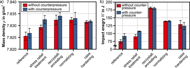 |
| Fig. 6: a) mass density measurements of heat treated parts with high damage levels after forming (extruded without counterpressure) and parts with less damage (with counterpressure) and b) impact energy from Charpy tests. The differences between the specimen with and without counterpressure decrease when heat treatment takes place above recrystallization temperature. |
The trend of decreasing differences between the specimens extruded with and without counterpressure is also observed in Charpy impact tests. The increased impact energy of the specimen extruded with counterpressure remains after stress relief treatment. As soon as recrystallization takes place during the heat treatment, the differences vanish (Fig. 6b). The results indicate that damage-controlled forming is only relevant to forming stages after the last heat treatment step.
Damage in Cold Forging Processes (WP 3)
To control damage in a broad variety of cold forging processes (including backward can extrusion, forward hollow extrusion, ironing and upsetting) the effect of process parameters on damage in the cold forged component was studied numerically. In backward can extrusion, large hydrostatic pressure is present in the forming zone (η < -1), independently of all process parameters. Thus, void closure is expected. This was validated by SEM-measurements for extrusion strains εex = 0.7 and εex = 1.2. The same holds true on the central axis in upsetting. However, on the outer radius positive triaxialities are observed, which are increased for larger upsetting ratios and higher friction coefficients. In forward hollow extrusion and ironing, high extrusion strains and low shoulder opening angles result in less damage. Ironing shows larger triaxialities in the forming zone compared to forward hollow extrusion for the same extrusion strain and shoulder opening angle.
Application of Damage-Control to Process Sequences (WP 4)
Based on the result of the previous work packages, complex process sequences with a known amount of damage can be designed. To demonstrate this, two different process sequences containing the processes of backward can extrusion, forward hollow extrusion and ironing are considered (Fig. 7). Both sequences result in the same product geometry. However, the damage in one of the routes is decreased.
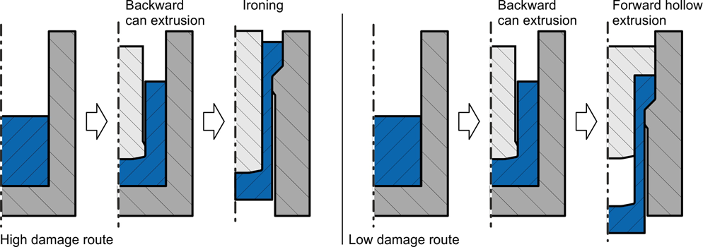 |
| Fig. 7: Process routes to manufacture geometrically identical complex cold forged parts with different amounts of damage. |
To separate the effect of damage from work hardening, the routes were chosen in a way that equal strain distributions are obtained in both parts. Tools for both process routes were manufactured and the parts were successfully formed. Validation of the predicted void area fractions by SEM-measurements and testing of the final product performance will be conducted until the end of the 2nd funding period.
Summary and Conclusion
In the 1st funding period, the hypothesis that damage during cold forging can be controlled by lowering the triaxiality was proven. For the first time the effect of hydrostatic stress on damage was verified isolated from the effect of plastic deformation. Furthermore, it was demonstrated that damage significantly influences product performance in terms of elastic stiffness, fatigue strength and impact toughness. In the 2nd funding period, this evidence was extended to complex process routes involving various deviatoric stresses, load path changes and heat treatments. The processes of rod and hollow extrusion were not only investigated to manufacture parts with increased performance, but were also established as fundamental laboratory tests to specifically prescribe hydrostatic and deviatoric stresses for the physical investigations of damage mechanisms in project areas B and C.
The immense amount of damage quantification in project A02 during the 2nd funding period was carried out utilizing the automated, large-area SEM-methodology developed by project B04. This methodology was transferred and implemented at the IUL and verified by comparative measurements at the GFE in close cooperation with project B04 and the working group “efficient damage characterization and damage mechanisms”.
The obtained observations of damage evolution under complex load paths were described by a simple void evolution equation to predict void area fractions for various cold forged parts. However, a quantitative prediction of product performance for various cold-forged parts and materials remains challenging, as not all phenomena, e.g. the influence of closed voids or damage in other types of materials, are fully understood yet.
Project- and subject-related ist of publications
| [Bar07] | Barsoum, I., Faleskog, J., 2007, Rupture mechanisms in combined tension and shear - Experiments, International Journal of Solids and Structures, 44(6), pp. 1768-1786, DOI: 10.1016/j.ijsolstr.2006.09.031. |
| [Bai08] | Bai, Y., Wierzbicki, T., 2008, A new model of metal plasticity and fracture with pressure and Lode dependence, International Journal of Plasticity, 24(6), pp. 1071-1096, DOI: 10.1016/j.ijplas.2007.09.004. |
| [Bay97] | Bay, N., 1997, Cold forming of aluminium - state of the art, Journal of Materials Processing Technology, 72(1), pp. 76-90, DOI: 10.1016/S0924-0136(97)00152-0. |
| [*Git23a] | Gitschel, R., Hering, O., Schulze, A., Tekkaya, A. E., 2023, Controlling Damage Evolution in Geometrically Identical Cold Forged Parts by Counterpressure, J. Manuf. Sci. Eng., 145(1), p. 011011. DOI: 10.1115/1.4056266. |
| [*Git23b] | Gitschel, R., Schulze, A., Tekkaya, A. E., 2023, Void nucleation, growth and closure in cold forging: An uncoupled modelling approach, Advances in Industrial and Manufacturing Engineering, 7, p. 100124. DOI: 10.1016/j.aime.2023.100124. |
| [*Guh23] | Guhr, F., Gitschel, R., Barthold, F. J., Tekkaya, A. E., 2023, Numerical Optimisation of Damage in Extrusion Processes, Proceedings in Applied Mathematics and Mechanics, DOI: 10.1002/pamm.202300199. |
| [Her20] | Hering, O., Tekkaya, A. E., 2020, Damage-induced performance variations of cold forged parts, Journal of Materials Processing Technology, 279 DOI: 10.1016/j.jmatprotec.2019.116556 |
| [Hen15] | Henschel, S. and Krüger, L., 2015, Effect of inhomogeneous distribution of non-metallic inclusions on crack path deflection in G42CrMo4 steel at different loading rates, Frattura ed Integrità Strutturale, 9(34), DOI: 10.3221/IGF-ESIS.34.35. |
| [Kon22] | Kong, X., Helfen, L., Hurst, M., Hänschke, D., Missoum-Benziane; D., Besson, J., Baumbach, T., Morgeneyer, T. F., 2022, 3D in situ study of damage during a ‘shear to tension’ load path change in an aluminium alloy, Acta Materialia, 231, DOI: 10.1016/j.actamat.2022.117842. |
| [*Lan23] | Langenfeld, K., Lingnau, L., Gerlach, J., Kurzeja P., Gitschel, R., Walther, F., Kaiser, T., Clausmeyer T. 2023, Low cycle fatigue of components manufactured by rod extrusion: Experiments and modelling, Advances in Industrial and Manufacturing Engineering, 7, p. 100130, DOI: 10.1016/j.aime.2023.100130 |
| [Lan08] | Lange, K., Kammerer, M., Pöhlandt, K., Schöck, J., 2008, Fließpressen - Wirtschaftliche Fertigung metallischer Präzisionswerkstücke, Springer Berlin, Heidelberg, DOI: 10.1007/978-3-540-30910-9. |
| [Oya80] | Oyane, M., Teisuke, S., Kunio, O., Susumu, S., 1980, Criteria for ductile fracture and their applications. J. Mech. Work. Technol. 4, pp. 65–81, DOI: 10.1016/0378-3804(80)90006-6. |
| [Qay22] | Qayyum, F., Umar, M., Elagin, V., Kirschner, M., Hoffmann, F., Guk, S., Prahl, U., 2022, Influence of Non-Metallic Inclusions on Local Deformation and Damage Behavior of Modified 16MnCrS5 Steel. Crystals. 12(2), pp. 281, DOI: 10.3390/cryst12020281. |
| [Ric69] | Rice, J.R., Tracey, D.M., 1969, On the ductile enlargement of voids in triaxial stress fields, J. Mech. Phys. Solid. 17 (3), pp. 201–217. DOI: 10.1016/0022-5096 (69)90033-7. |
|
[Wei06] |
Weiß, A., Gutte, H., Scheller, P. R., 2006, Deformation Induced Martensite Formation and its Effect on Transformation Induced Plasticity (TRIP), Steel research international 77(9-10), DOI: 10.1002/srin.200606454. |
| [Zis22] | Zistl, M., Brünig, M., Gerke, S., 2022, Analysis of damage and fracture behavior in ductile metal sheets undergoing compression and shear preloading. International Journal of Material Forming 15, 59, DOI: 10.1007/s12289-022-01705-4. |