Project history
During the second funding period, sub-project A06 focused on the quantitative description and prediction of the interactions between the process parameters and setup of deep drawing and stretch indenting and the ductile damage induced in the workpiece. The aim of the investigations was to achieve targeted, knowledge-based process design by controlling the damage state, thereby trying to enhance the performance of the workpieces. To achieve this, geometrically similar workpieces made of dual phase steel DP800 with varying process parameters and setup were manufactured and compared to each other. The parameters included the die radius, the punch velocity and the friction. Additionally, the setup consisted of multi-stage forming in the form of redrawing/restretch indenting and reverse drawing/indenting. The focus was on a rectangular cup characterized by an asymmetric material flow and a concave radius, as well as a U-profile to cover the most commonly occurring geometric features in three-dimensional sheet metal forming. For deep drawing and stretch indenting, it was successfully demonstrated that variations in the process parameters and setup lead to altered load paths and ultimately to different damage distributions in the workpiece. The effect of the different damage distributions on the resulting performance within the scope of experimental investigations are part of ongoing investigations, whereby initial results already indicate a tendency towards a positive influence on performance.
However, the sub-project concludes at the end of the second funding period. As described in detail in the introductory section, the activities of the sub-project will be continued in a transfer project due to the great industrial interest.
Report
The main sub-objectives of sub-project A06 in the second funding period were:
-
- How can the findings from the first funding period be transferred to the deep drawing of complex geometries?
- Which load paths occur when DP800 is stretch indented and what damage occurs in the process?
- How can the load paths during deep drawing be modified and thus the damage influenced by a targeted change in process parameters and process setup?
- How can the performance of components with complex geometric shapes be increased through the targeted design of load paths during deep drawing and deep stretch indenting?
- To what extent can the models and methods developed for DP800 be transferred to other materials?
In accordance with the objectives, a work program including different work packages (WP) was developed and the results achieved are explained and related in this report.
Variation and modeling of friction
During the deep drawing process, local variations in contact normal stresses σN, relative velocities vr, and temperatures T can occur, even when the punch velocity vP and blank holder force Fbh are kept constant. To accurately describe the effect of friction on the development of damage the friction model proposed by Klocke was chosen [Klc15], and its coefficients (i, j) were calibrated using strip drawing tests (WP1) (Eq. 1).
![]()
The contact normal stress σN and relative velocity vr were varied, with their maximum values derived from numerical investigations (σN < 75 MPa, vr < 15 mm/s). In order to generate different tribo-systems and examine their influence on the damage state, ground tool surfaces, tool surfaces processed transversely with a positive overlap using machine hammer peening (MHP) and tool surfaces processed with MHP without overlap were employed (Fig. 1). Sandblasted tool surfaces were not used as the applied surface structures exhibited high wear and quickly wore off.
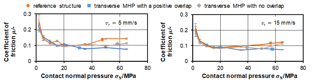 |
| Fig. 1: Coefficient of friction μ in dependence of relative velocity vr and contact normal pressure σN |
Peening tool surfaces with two MHP parameter sets affected friction in strip drawing tests. Both structures showed a lower friction coefficient µ, especially at higher contact normal stress σN. The reference structure's µ increased from σN = 20 MPa, while MHP structures maintained a relatively constant µ. It is hypothesized that at a certain σN, lubricant is forced out, increasing µ for the reference structure, but not for MHP structures, which retain lubricant in introduced pockets. Additionally, µ decreases with increasing relative velocity vrel, suggesting increased friction-reducing hydrodynamic effects. The final choice, based on least squares analysis, was the ground reference structure and MHP-transversely processed tool surface with positive overlap, exhibiting the lowest friction values (Table 1).
Table 1: Overview of the coefficients of the friction model according to Klocke
|
Reference |
Transverse MHP with positive overlap |
||
| c |
= 0.3329 |
c |
= 0.332 |
| i |
= -0.2358 |
i |
= -0.3183 |
| j |
= 0.1569 |
j |
= -0.1138 |
Influence of process parameters and setup on load paths and damage state
The influence of process parameters and setup during deep drawing and stretch indenting on load paths in form of triaxiality η, lode angle parameter θ, von Mises equivalent stress σvm and plastic equivalent strain φpl as well as on the damage state was investigated numerical by using Abaqus/Explicit. To predict the damage state, the coupled damage model calibrated by S01, based on Lemaitre's approach, was applied. In addition, the numerical investigations were supplemented with experimental investigations. The damage states after forming in selected areas derived from the numerical analysis were examined in the form of void area fractions. Corresponding scanning electron microscopy (SEM) images were analysed using the machine learning algorithm developed in B02. This enabled a comparison of the damage state predicted by the Lemaitre model after forming and the damage actually resulting in the experiment.
For the investigations, geometrically similar workpieces were compared at a moment shortly before failure. As the time of failure respectively the maximum possible punch stroke sSt without failure was different for each variant, the time of analysis was based on the variant that failed first and was indicated by the punch stroke sSt. The numerical load path analysis focused on a reference point chosen at the outer bend of the bottom-to-wall transition (Fig. 2), aligning with potential future applications for the workpiece. To numerically analyse the damage distribution, a parameter x was introduced, passing through the corner of the component considering the rectangular geometry or the exact middle of the component considering the U-profil. In the numerical analysis, the die radius rD was modified and the process setup was changed considering redrawing/restretch indenting and reverse drawing/stretch indenting. The punch speed was only considered experimentally, as strain rate dependency is not yet covered by corresponding damage models. The deep drawing process is schematically depicted in Fig. 2. The kinematics and dimensions similarly apply to the stretch intending process, which additionally featured a drawing bear in the die and blank holder. The sheet thickness was set to = 1.5 mm and the punch speed to = 5 mm/s. The punch had a length lp of lp = 100 mm, a width wp of wp = 50 mm and a corner radius rpC of rpC = 10 mm. The drawing clearance c was c = 1.8 mm. The punch radius was fixed at rp = 3 mm and the reference die radius rD at rD = 3 mm. The sheet had a length ls,rec. of ls,rec. = 142 mm, a width ws of ws = 92 mm and a corner radius rs of rs = 10 mm.
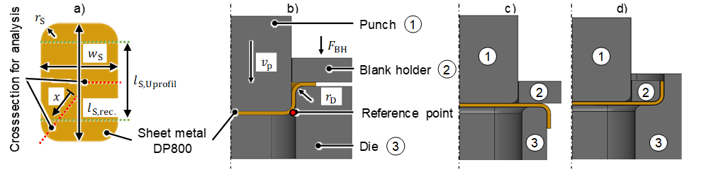 |
| Fig. 2: Schematic illustration of a) dimension of sheet metal before forming b) deep drawing, c) redrawing and d) reverse drawing process |
Deep drawing of rectangular cups
For deep drawing of rectangular cups (WP1), it was shown that varying the die radius rD affects the load paths. The most significant difference could be found in the equivalent plastic strain φpl which increased with a decreasing die radius rD. To derive a value for quantitative comparison, the integrals of the respective load path parameters over the equivalent plastic strain φpl were introduced (Fig. 3). The integral of the triaxiality ∫ηdφpl, the lode angle parameter ∫θdφpl and the von Mises equivalent stresses ∫σvmdφpl thereby decrease with increasing die radius rD. The die radius rD appears to cause the necessary flange pull force to vary, resulting in a greater or lesser extent of sheet thinning at the beginning of the deep drawing process. Accordingly, a smaller die radius leads to an inhibition of the material flow from the flange area, while a larger die radius rD promotes it.
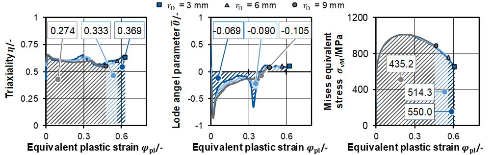 |
| Fig. 3: Load paths considering a variation of die radius rD during deep drawing of rectangular cups |
Along with the larger equivalent plastic strain φpl with increasing die radius rD, a higher numerically predicted maximum damage parameter Dmax was also observed (Fig. 4). Thereby maximum damage parameters Dmax of Dmax,r=3mm = 0.541, Dmax,r=6mm = 0.437 and Dmax,r=9mm = 0.298 were numerically predicted. Regardless of the die radius rD, the numerically predicted damage maximum Dmax was mainly localized in the corner of the component. The bottom did not display any damage. However, for rD = 3 mm damage could also be found in the wall. The determined void area fractions support the numerical analysis qualitatively. The die radius of rD = 3 mm reached 0.0966 %, followed by rD = 6 mm with 0.0337 % and by rD = 9 mm with 0.0320 %.
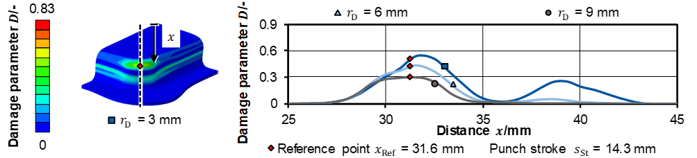 |
| Fig. 4: Damage distribution considering a variation of die radius rD during deep drawing of rectangular cups |
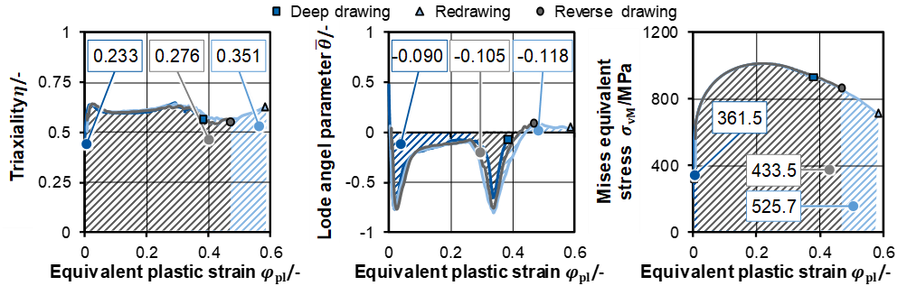
With variation of the process setup considering a deep drawn rectangular cup (WP1), it was shown that the stress states show similar characteristics. The equivalent plastic strain φpl, however, differed (Fig. 5). Regarding the integrals of triaxiality ∫ηdφpl, the highest value was achieved by redrawing, followed by reverse drawing and deep drawing. This trend is also applicable to the integrals of the lode angle parameter ∫θdφpl as well as the von Mises equivalent stress . In accordance with the variation of the die radius rD, it appears that the variation in equivalent plastic strain φpl phenomenon can also be attributed to the flange pull force. When forming the bottom of the workpiece, until the material flow comes mostly from the flange area, a different force is needed for each process setup, similar to using different die radii rD. Because of the initial forming of the workpiece, more force is required for multi-step forming than for deep drawing, which can also be seen considering the punch forces needed. As a result, depending on the process setup, sheet thinning at the reference point was more pronounced.
 |
| Fig. 5: Load paths considering a variation of process setup during deep drawing of rectangular cups |
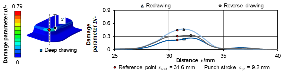
Considering the numerically predicted damage distribution in the corner of the workpiece of the rectangular cup shown in Fig. 6, an analogous tendency to the load paths can be observed. While no damage was introduced in the bottom of the workpiece by deep drawing or multi-stage forming, there is a higher numerically predicted damage parameter Dmax for redrawing in the transition towards the wall, followed by reverse drawing and deep drawing. Furthermore, the numerically predicted area affected by damage in the corner of the workpiece after deep drawing is significantly lower than for reverse drawing and redrawing. The maximum numerically predicted damage parameters Dmax reached Dmax,deep drawing = 0.263, Dmax,reverse drawing = 0.320 and Dmax,redrawing = 0.464. Considering the determined void area fractions, a similar tendency can be observed. Deep drawing reached 0.0424 %, redrawing 0.0578 % and reverse drawing 0.0555 %.
 |
|
Fig. 6: Damage distribution considering a variation of process setup during deep drawing of rectangular cups |
In order to investigate the influence of friction on the damage state the rectangular cup with an asymmetrical material flow was used as a test case (WP1). The asymmetrical material flow (Fig. 7a)) was chosen as it is known to be sensitive to friction and it allows to study the effect of friction on the damage state of the workpiece. In order to do so, a friction ratio µi/µj was introduced (Fig. 7b)) using the tool surfaces processed transversely
 |
| Fig. 7: a) Geometry of component, location of analysis and b) introduction of the friction ratio |
with a positive overlap using MHP (ST) and the ground tool surface (Ref). Due to the flow restriction of the material in the corner of the rectangular cup, the tool surface with the lower friction coefficients µ determined in the strip drawing test was used in this area. The ground tool surface was provided on the long, straight sides, while the corner of the tool surfaces were processed transversely with a positive overlap using MHP.
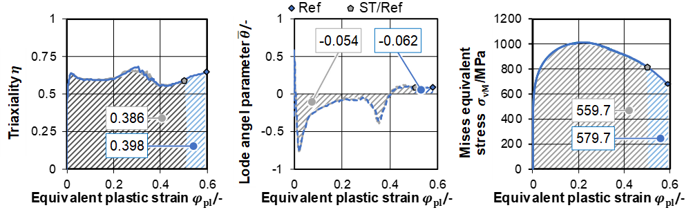
Fig. 8 shows the load path considering the adapted friction. It was determined that the load paths differ especially in the equivalent plastic strain φpl, see Fig. 8. For the introduced friction ratio µi/µj, the equivalent plastic strain φpl was lower.
 |
| Fig. 8: Load paths considering a variation of friction during deep drawing of rectangular cups |
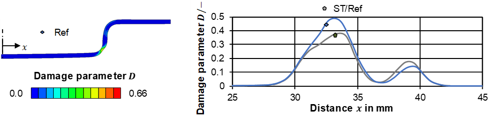
Observing the numerically predicted damage distribution in the cross-section of the corner of the rectangular cup in Fig. 8, it becomes apparent that the introduced friction ratio µi/µj lowered the maximum numerically predicted damage parameter Dmax in the area of the transition from floor to wall. At the same time, however, the numerically predicted damage parameter Dmax in the wall increased. The reason for this phenomenon is believed to be the lower friction coefficient in the corner, which allows for more material flow and less inhibition at the start of the process. At lower coefficients of friction µ, the material tends to follow the punch more closely, resulting in less sheet thinning in the corner at the beginning of the process. However, as the punch stroke sst increases, the equivalent plastic strain φpl that the material experiences also increases, due to the larger amount of material that attempts to flow over the die radius rD, simultaneously.
 |
| Fig. 9: Damage distribution considering a variation of friction during deep drawing of rectangular cups |
Additionally, as more material is formed, the forces required for forming also increase leading to an increase of the induced stresses in the component. Since damage is always correlated with equivalent plastic strain φpl, it seems that the maximum numerically predicted damage parameter localizes further up the wall as the friction coefficient ratio µi/µj increases. The determined void area fractions support the numerical results reaching 0.0954 % for ST/Ref and 0.0966 % for Ref.
By varying the punch speed vp, it was experimentally observed that an increase in the punch speed leads to an increase in the void area fraction. The determined void area fractions reached 0.0674 % for vp = 50 mm/s and 0.0424 % for vp = 5 mm/s. However, further investigations are necessary in order to identify the underlying mechanisms with regard to damage. To this end, investigations into the void size distributions and the dominant damage mechanisms are planned for the current funding period.
Stretch indenting of U-profiles
In order to investigate the influence of the process parameters and setup on the load paths and the damage state during stretch indenting (WP2), a U-profile rather than a rectangular cup was investigated numerically in contradistinction to deep drawing. This is due to the forming limit of the dual-phase steel used. As in the case of deep drawing, the load paths based on the variation of the die radius rD paths exhibited differences in particular in the equivalent plastic strain φpl. Considering the damage distribution, the numerically predicted damage parameter was shown to be almost identical for all die radii rD in the area of the bottom, the transition and the flange. In the wall, however, the damage decreased with increasing die radius rD. The experimental investigations have shown that the maximum profile depth is significantly below the numerically predicted depth. It is assumed that the very high contact normal stresses occurring result in very high friction values in the flange area, which in turn lead to high tensile stresses in the wall and ultimately to failure earlier then numerically predicted. Because of this the focus of the project was shifted to deep-drawn U-profiles. However, investigations into the geometry of the drawing beads were carried out in cooperation with C05. The focus was on reducing the damage in the defined reference point by optimizing selected geometric dimensions of the drawing beads, also in order to increase the profile depth. The corresponding results as part of WP3 can be found in the report of C05.
Considering the variation of the process setup, it was noticeable that the triaxiality η and lode angle parameter θ courses as well as the von Mises equivalent stress σvm in reverse stretch indenting and restretch indenting differ from those of classical stretch indenting. While triaxiality η and von Mises equivalent stress σvm hardly differ in reverse stretch indenting and restretch indenting, the level of the lode angle parameter θ course in reverse stretch indenting was clearly below that of restretch indenting, although the characteristics of the course are observed to be rather similar.
The numerically predicted damage distribution showed that there is a pronounced thinning of the sheet in the area of the reference point. Due to the limited maximum possible profile depth, it was decided not to pursue different process setups during stretch indenting experimentally. Instead, the focus was shifted to deep-drawn U-profiles. A detailed description of the investigations and the results regarding stretch indenting can be found in [*Mül23a]
Influence of the damage state on performance
The performance tests as part of WP1 are currently in progress. Cyclic performance tests are planned for both the rectangle and the U-profile. These serve to quantify the influence of the damage on the corresponding performance of the components. However, initial studies have already shown a tendency for the modified damage distribution to have a positive influence on performance.
Transferability to other materials
In order to evaluate the qualitative transferability of the results to other materials, components with selected process parameters were deep-drawn from the aluminum alloy A6010 as part of WP4 with regard to the work planned in sub-project A10 in the third funding period. The rectangular geometry from WP1 was used for this. The drawing ring radius rD = 3; 9 mm was selected as varying process parameters. The unvaried process parameters were identical to the investigations of the DP800. Before deep-drawing, the sheets were heat-treated and brought to the soft-annealed state. After deep drawing, the components were characterized with regard to the damage state in the same way as WP1. In order to identify the influence of the subsequent common heat treatment of the material on the damage state after deep drawing, half of the components were subsequently solution annealed, artificially aged and also characterized with regard to the damage state. The results showed that the components after deep drawing before heat treatment showed a low void area fraction induced by the forming process because of the high ductility of the material despite an increase in the punch stroke by 50% and thus the plastic strain. As a result, the influence of the heat treatment on the damage state could not be assessed in initial investigations. However, cavities in the form of fusions consisting of Mg2Si could be identified on the SEM images. These are influenced by the heat treatment process, particularly in terms of their shape. Further investigations into the phenomena that occur and the transferability of the results from DP800 to aluminum will be conducted in this funding period. This includes increasing the punch stroke within the scope of the feasibility of the selected tool in order to reach closer to the failure limit and thus increase the void area fraction.
Influence of predamage and microstructure on the damage state
As part of WP5, the influence of cold rolling parameters on the microstructure and damage, especially on its evolution during deep drawing was investigated, in collaboration with A04. Therefore, steel blocks from S355 steel were hot rolled to a thickness of hh = 3 mm, cold rolled to hc = 1.5 mm, and heat treated into a DP800 dual phase steel. During cold rolling, the pass reduction was varied as Δh = 0.10; 0.75 mm. Circular blanks with a diameter of d0 = 85 mm were water jet cut from the DP800 sheets. These blanks were then deep drawn into rotationally symmetrical cups with a diameter of d1 = 60 mm with variation of the die radius rD = 3; 9 mm. The rolled material and the cups were characterized with regard to damage in the form of voids in the material using SEM and a convolutional neural network. It was observed that raising the pass reduction during cold rolling does not considerably alter the void area fraction in the rolled material. However, it does lead to the formation of a greater quantity of small voids. This is due to the more pronounced compressive stress state which is caused by the increase in the pass reduction. The higher occurrence of voids can subsequently expand during deep drawing, leading to a rise in the void area fraction relative to the material rolled with a lower pass reduction. Further details and a detailed description of the investigations can be found in [*Nic21].
Investigations exceeding the work program
Influence of process parameters and setup on load paths and damage state during deep drawing of U-profiles
In addition to the investigations of the rectangular cup during deep drawing and the numerical investigations of the U-profile during stretch indenting, further studies were carried out on the correlation of load paths and damage state of deep-drawn U-profiles. For this purpose, U-profiles were analyzed in the same way as the investigations with the rectangular cup. The experimental setup, the reference point and the unvaried process parameters were identical and can be found with detailed results in [*Mül23b]. Similar to the rectangular cup and the reference point at the outer bend, it was shown that the stress parameters of the load paths have similar characteristics with variation of the die radius rD, while the equivalent plastic strain φpl differs more significantly. For the damage distribution, it was apparent that the maximum numerically predicted damage parameter Dmax can be shifted from the wall to the bottom-to-wall transition. At the same time the occurring damage can be significantly reduced. By varying the process setup, it was shown that the load paths in the reference point can hardly be influenced, but a completely new damage distribution results in the wall of the component, whereby the damage maximum is also shifted within the component. The numerical investigations already conducted will be supplemented with experimentally determined void area fractions and performance tests in the current funding period.
Project- and subject-related list of publications
| [Klc15] | Nick, M., Liebsch, C., Müller, M., Weiser, I. F., Hirt, G., & Bergs, T., 2021. Influence of pass reduction in cold rolling on damage evolution in deep drawing of rotationally symmetric cups. In: IOP Conference Series: Materials Science and Engineering, DOI: 10.1088/1757-899X/1157/1/012050 |
| [*Nic22] | Nick, M., Müller, M., Voigts, H., Weiser, I.F., Herrig, T. & Bergs, T.,2022. Effect of friction Modelling on damage prediction. In: Defect and Diffusion Forum, DOI: 10.4028/p-29o20d |
| [*Mül22] | Müller, M., Weiser, I.F., Herrig, T. & Bergs, T., 2022. Numerical prediction of the influence of process parameters and process set-up on Damage Evolution during Deep Drawing of Rectangular Cups. In: Engineering Proceedings, DOI: 10.3390/engproc2022026006 |
| [*Mül23a] | Müller, M., Weiser, I.F., Herrig, T. & Bergs, T.,2023. Influence of process parameters and process set-up on damage evolution during stretch drawing of u-shaped profiles. In: Materials Research Proceedings, DOI: 10.3390/engproc2022026006 |
| [*Mül23b] | Müller, M., Herrig, T. & Bergs, T., 2023. Numerical analysis of the load paths and the resulting damage evolution during deep drawing of dual-phase steel. In: IOP Conference Series: Materials Science and Engineering, DOI: 10.1088/1757-899X/1284/1/012006 |
| [*Mül23c] | Müller, M., Fehlemann, N., Herrig, T., Lenz, D., Könemann, B., Bergs, T. & Münstermann, S.,2023. Forming limit of dual phase steel: an experimental and numerical investigation. In: Proceedings of the 14th International Conference on the Technology of Plasticity - Current Trends in the Technology of Plasticity, DOI: https://doi.org/10.1007/978-3-031-40920-2_ 2 |
| [*Som23] |
Sommer, J., Müller, M., Herrig, T. & Bergs, T., 2023. Simulative and empirical investigation of test specimen geometries for the determination of forming limit states in the tensile-compression range for austenitic stainless steel foil material. In: Proceedings of the 14th International Conference on the Technology of Plasticity - Current Trends in the Technology of Plasticity, DOI: 10.1007/978-3-031-42093-1_25 |