Summary
The primary goal of this project is to identify the potential for damage control in sheet metal bending and to assess its influence on product performance. The findings enabled damage-controlled sheet forming, but also allow for the quantitative prediction of the product performance such as formability, Charpy toughness and stiffness. In the 1st funding period (FP), the influence of triaxiality on damage evolution and product performance in monotonic bending processes was investigated for DP800. By separating other effects, such as hardening and residual stresses, it was proven that component performance can be increased by damage controlled forming. A novel bending process, the RSS-bending (radial stress superposed bending) was invented, with which the superposition of compressive stresses on the outer fiber is achieved during bending. This reduces the occurring void area in the bent part in comparison to conventional air bending. For the quantification of damage, density and SEM-image analyses were conducted in accordance to the methods developed in B02. Through damage control, product properties were improved: stiffness increased by 8% and the absorbed energy during impact tests increased by 31%. In the 2nd FP damage control was further studied in processes with non-monotonic load paths, along process chains and during heat treatment (austenitization and quenching) of 22MnB5. In roll forming, damage control for DP800 was achieved by stress superposition through additional elastomer rollers. The stiffness of such roll formed parts increased by 9% and the remaining formability increased by 15% compared to traditional process setups. Related to multi-step sheet metal forming processes, orthogonal load direction changes have been identified to produce (up to 70%) less damage for DP800 than monotonic loads. The effect of the stress state, in particular the triaxiality and Lode angle parameter, was separated numerically from other effects, such as kinematic hardening, to isolate the specific influence of load direction changes on damage evolution, which was quantified by experimentally determined void area fractions. Numerical simulations revealed that voids between two martensitic islands are compressed, i.e. shrink in size, even at positive triaxialities, if a tensile load is applied orthogonally to the pre-strain direction. This provides a new tool in damage control. Compared to DP800, during press hardening of 22MnB5, different damage mechanisms such as cracking and decohesion of cementite, carbides and inclusions were identified. To understand the effect of austenitization and quenching on the damage evolution, void analyses of bending specimens before and after such heat treatment were performed. The results showed that voids can actually decrease in size during heat treatment under press hardening conditions. However, the damage distribution after heat treatment is still influenced by the formerly induced stress and strain states during forming.
While the 1st FP aimed to acquire the fundamental understanding of mechanisms driving damage evolution, the 2nd FP focused on the control of damage to promote less evolution in multi-stage sheet metal forming and during heat treatment. Now, the goal of the 3rd FP is to understand the necessary conditions for void shrinkage, closure and eventually healing in cyclic load paths and during hot forming.
The investigation of the 3rd FP will be devoted to following three new research themes: Firstly, the effect of cyclic loading during forming with changes between positive and negative triaxialities (hydrostatic part of stresses) will be investigated. For this purpose, a modified lab setup for the Continuous Bending under Tension (CBT) test will be developed. These tests will allow to observe under which conditions voids shrink, close and grow again and if this effect increases or fades with increasing cycles. To check the transferability of the new knowledge based on the results regarding controlling damage evolution by stress state and cyclic loads, the forming process Single Point Incremental Forming (SPIF) is employed to produce damage-controlled high performance parts made of industrially manufactured DP800 as well as damage-tolerant DP800 from A04. Secondly, the study of the necessary conditions for void shrinkage, closure and healing are investigated for the hot sheet metal forming process of press hardening 22MnB5. Therefore, the thermo-mechanical conditions are identified by a variation of stress states, strain paths and forming temperature. This is achieved by superposition of compressive stresses and varying degrees of deformation. Thirdly, aluminum AA6082 is studied as a new material class to be used in sheet metal bending. While in the previously investigated DP800 the most frequent damage mechanism is martensite cracking, a new material class offers new insights to the influence of the load path, load direction changes and cyclic forming processes on the damage behavior of this new material.
Report and current state of research
The results from the first three years of the 2nd four-years funding period are presented in the following with references to the work packages of the 2nd period.
Bending of V-profiles (WP2)
In the first funding period, it was shown that damage evolution in DP800 steel during bending processes can be controlled by superimposing compressive stresses during deformation, which leads to improved product performances [*Mey19b]. In the second FP, to analyze damage evolution along process chains with multiple bending operations, roll forming is studied (Fig. 1, 2a). In this process the sheet is exposed incrementally to tensile and/or compressive loads along the axial and width direction depending on the target geometry and process parameters. The process was modified by adding elastomer rollers (Fig. 2b) with the aim to control damage evolution and improve product performance by influencing the stress state during forming [*Len23a].
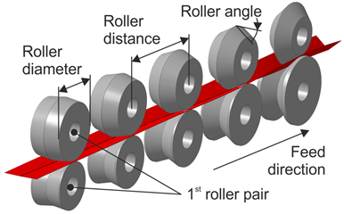 |
| Fig. 1: Roll forming setup |
The forming zone in roll forming initiates before the contact zone between the rollers, while depending on the bending angle and the width of the sheet. Elastomer rollers can be compressed and therefore extend the contact zone, so a large proportion of the load path can be positively influenced (Fig. 2b) by compressive stress superposition. The geometry of the elastomer rollers was designed through a numerical model including the C02 model [Spr20] with the aim to reduce damage evolution. Through the process modification with elastomer rollers, the triaxiality is lower over the whole forming process (Fig. 3a). The average triaxiality¹ is 0.58 for the conventional process and 0.48 for the setup with elastomer rollers. However, the maximum strain is increased by about 6% using the elastomer rollers, a finding derived from numerical and experimental results.
![]()
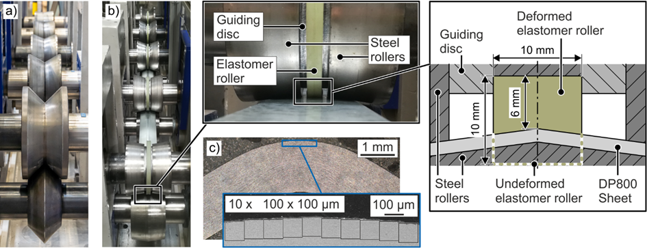 |
| Fig. 2: Experimental setup of roll forming a) without and b) with elastomers. c) Area for determination of void area fraction |
These two effects work oppositely regarding damage evolution, with lower triaxiality reducing and higher strains increasing damage. The damage model by C02 predicts an overall lower damage evolution in the roll formed parts with elastomer rollers (Fig. 3b) indicating that the effect of triaxiality dominates damage as compared to the plastic strain in this case. For the validation of these results, the void area fraction was measured on the roll formed specimens (Fig. 2c) by SEM imaging methods as developed by B02 [*Mey19a]. It is lower by about 33% in comparison to the values of roll formed parts without elastomer rollers (Fig. 3c). This validates the modelling in the sense, that the positive influence of damage control by lowering the triaxiality outcompetes the negative influences of higher strains for a given part geometry.
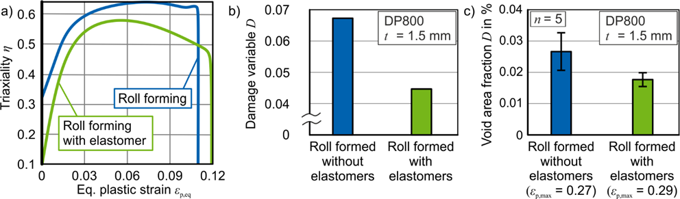 |
| Fig. 3: a) Triaxiality on the outer fiber with and without elastomer in the first stage, b) computed damage values with the C02 model, and c) measured void area fraction in roll formed parts [*Len23a] |
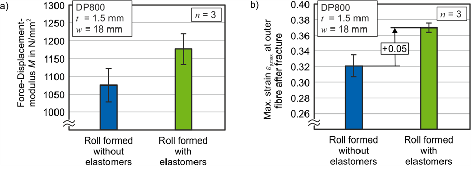
The influence of the stress superposition on the product performance of the manufactured V-sections is identified by analysis of effective stiffness and remaining formability. The experimental setup as described by Meya [*Mey19b] is used to determine the overall stiffness.
 |
| Fig. 4: Product performance of bent parts regarding a) stiffness and b) remaining formability from roll forming until fracture in air bending [*Len23a] |
The remaining formability of the roll formed specimens is tested by an additional bending test with two rollers acting as dies. The force-displacement modulus, a quantity representing the product stiffness, is defined as the slope of the elastic response to the external load, prior to the onset of plasticity in the part. For the roll formed parts with elastomers, this modulus is 9% higher compared to the parts made without elastomers (Fig. 4a). The analysis regarding the remaining formability revealed that for damage-controlled parts, the fracture strain was 15% higher compared against conventional parts (Fig. 4b). It is concluded that the reduced damage values in roll forming correlate well with the improvements in the performance categories stiffness and remaining formability.
Until the end of the second FP, the ongoing work regarding process chains includes the investigation of damage evolution and product performance in profile bending processes, such as rotary draw bending and three-roller push bending with conventional and damage-tolerant DP800 sheets delivered by A04.
Influence of load direction w.r.t. the rolling direction on damage evolution (WP1, WP3 and WP4)
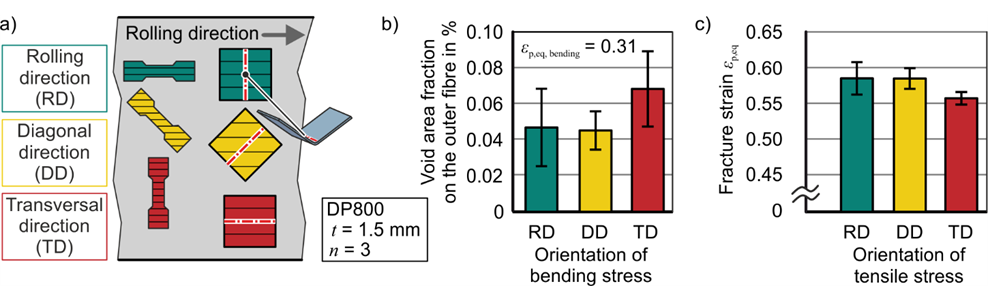
Recent observations have shown that the microstructure of the investigated DP800 is influenced by cold rolling before annealing [Pue20]. Hence, the martensite is mainly present in band-shaped structures and the different ferrite grains appear mostly elongated along the rolling direction (RD). Consequently, the influence of the loading direction relative to the rolling direction on damage evolution was evaluated. Therefore, single stage A80 tensile tests, in accordance with DIN 50125:2009-07, and bending tests up to a strain of 0.31 at the outer fiber were carried out (Fig. 5a). The subsequent determination of the damage values was done using the characterization methods as described in the new TRR Handbook (see WG Characterization). While the flow curves of the three orientations align (not shown), indicating plastic isotropy, the transverse direction (TD) specimen showed the lowest fracture strain (Fig. 5c) with the highest void area found using SEM imaging (Fig. 5b). In spite of the absence of a planar anisotropy, the damage evolution and fracture strain show a dependence on the loading direction w.r.t. rolling direction. As the texture orientation has an obvious influence on the damage evolution, this has to be considered in applying different loading paths (see next paragraph).
 |
| Fig. 5: a) Definition of load direction w.r.t. the rolling direction, b) damage evolution and fracture strain w.r.t. the rolling direction |
Changing of loading directions (WP1, WP3, WP4)
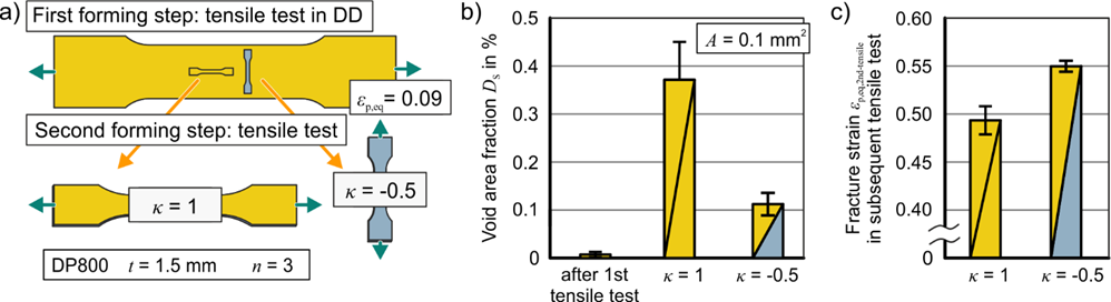
Many complex and multi-step sheet forming operations involve non-linear loading paths, which affect the materials hardening and fracture characteristics. Hardening behavior, fracture strains and damage evolution were first characterized for changing loading directions in 2-step tensile tests (Fig. 6a). To initially exclude the influence of the rolling direction, specimens were pre-strained in diagonal direction, so that the subsequent test is also oriented in a diagonal direction. In standard tensile tests, specimens of 60 mm width were pre-strained to a plastic strain of 0.09, which is prior to necking at a strain of 0.108. Afterwards, sub-specimens were cut out and loaded by tensile stresses in the same or the orthogonal direction to the pre-strain up to an equivalent plastic strain of 0.35, because up to this strain the geometry of specimen and therefore their strains are equal. To quantify strain path changes, the parameter κ proposed by Schmitt [Sch85]² is used for the classification of strain path changes with values between a monotonic strain path at κ = 1 and a strain path reversal at κ = -1. For the investigated two cases of the 2-step tensile tests, κ is equal to 1 (no change) and equal to -0.5 (Fig. 6a). The void area fractions were measured after the pre-strain and in the subsequent specimen. For both subsequent loading directions the damage increases compared to reference measurements after the 1st tensile test (Fig. 6b). Orthogonal changes of loading direction lead to lower damage evolution than monotonic loads, which enables a new process parameter for controlling damage in sheet metal forming of dual phase steels. Evaluating the product performance by means of localized fracture strain, which was captured by DIC, confirmed the results from the damage analysis, as higher fracture strains were observed at the specimens with an orthogonal load direction change (Fig. 6c, κ = -0.5).

 |
| Fig. 6: Tensile-tensile sequence: a) Void area fraction in tensile specimen after pre-strain and after subsequent uniaxial and cross loading; b) Fracture strain in second stage tensile test with and without a change of loading direction [*Len23b] |
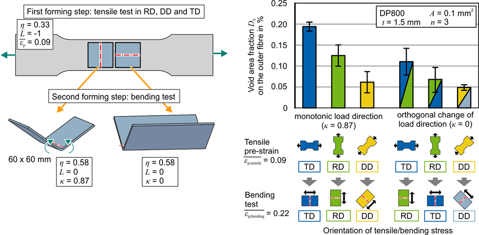
The tensile-tensile sequences enabled an isolated view on load direction changes, while keeping the load path (triaxiality and Lode parameter) constant. Regarding complex sheet metal forming processes, tensile-bending sequences are investigated, where not only the load direction is changed, but also the hydrostatic and deviatoric stress state (Fig. 7a). Therefore, bending tests are conducted, where the bending stresses are either aligned or orthogonal to the tensile pre-strain direction. The influence of the initial rolling process on damage evolution is assessed by additional tests in rolling direction and transverse direction (RD, TD). Damage evolution was found to be highest in TD, while the lowest damage evolution occurred at a load in diagonal direction (Fig. 7b).
 |
| Fig. 7: Tensile-bending sequence: Void area fraction after subsequent bending test in rolling direction (RD), diagonal direction (DD) and transverse direction (TD) [*Len23b] |
Also damage evolution after an orthogonal loading direction change differs for each sequence w.r.t. the rolling direction. It is concluded, that the rolling induced microstructure not only has an influence on damage evolution in monotonic loads, but also at strain path changes at κ = 0.87 and κ = 0. When comparing the RD-RD and RD-TD sequence, as well as the TD-TD and TD-RD sequence (Fig. 7b) the void area fractions are lower after an orthogonal change of loading direction in comparison to a monotonic load direction. The same holds true for the DD-sequences, however to a significantly lesser extent.
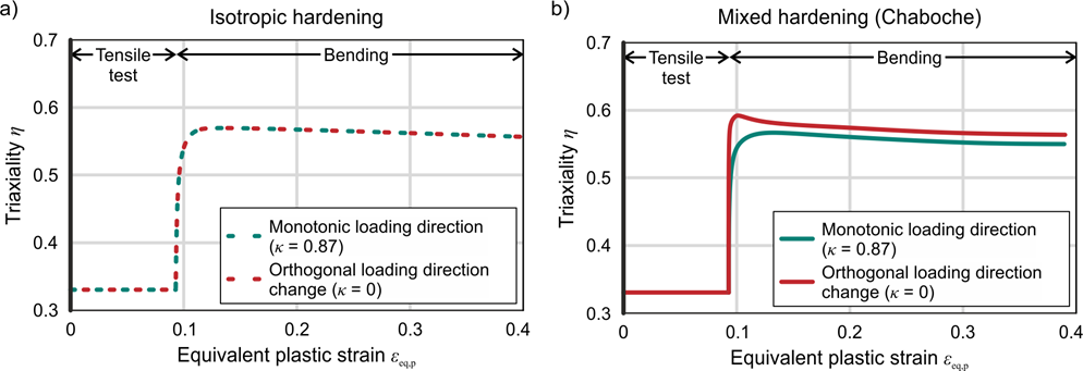
To consider anisotropic hardening, the stress state during the bending test is determined by a simulation with an anisotropic hardening model. The hardening behavior is assessed by the flow curves of the tensile-tensile test sequences. DP800 reveals anisotropic hardening behavior, for which the mixed isotropic-kinematic hardening model by Chaboche [Lem90] has shown good results [Den18].
Regarding the subsequent bending test, the plane strain condition with the assumption of isotropic hardening leads to a triaxiality of 0.58 and a Lode parameter of zero on the outer fiber for both monotonic and an orthogonal change of loading direction (Fig. 8a). The orthogonal loading direction change leads to an increased triaxiality in the subsequent bending operation in comparison to a monotonic loading direction when anisotropic hardening is accounted for (Fig. 8b). High triaxiality leads to higher damage evolution. Hence, regarding the macroscopic stress state, a lower damage evolution would be expected for monotonic loading directions, but experimental results indicate the opposite. This suggests that the influence of the hardening behavior is not the dominant effect for the different damage evolution and fracture.
 |
| Fig. 8: Effect of hardening model on triaxiality in bending test on the outer fiber after tensile pre-strain a) isotropic hardening, b) mixed hardening with Chaboche-model [*Len23b] |
An explanation for the observed lower damage in orthogonal strain path changes is given by the behavior of intra-martensite voids during loading direction changes. Analysis of voids in tensile tests by B02 [Med20] have shown that intra-martensite voids (cracking of a martensite grain) are orthogonal to the principal stress applied and are, hence, oriented transverse to the initial loading direction (Fig. 9a). Using an illustrative FE-based analysis (Fig. 9b), it can be shown that, when an orthogonal strain is applied to such a (simplified) microstructure, the initial void is compressed by the two surrounding martensite islands. Consequently, its void area shrinks. This phenomenon can explain the lower damage values found in orthogonal load direction changes compared to monotonic loads.
Ongoing investigations in cooperation with B02 aim to identify damage mechanisms in sequences of tensile and shear loading. A load path change from shear to tension was investigated in-situ by Kong [Kon22] on recrystallized AA2198 T8. Results have shown that flat cracks nucleate under shear load and subsequently grew and coalesced during tensile load. Current investigations with B02 will show, if a difference in damage mechanisms is found when comparing a shear-tensile load sequence to a tensile-shear sequence for DP800.
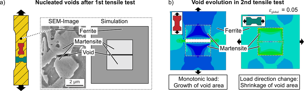 |
| Fig. 9: a) Position of voids in between two martensitic phases after pre-strain and its illustration in a FEM simulation b) Simulation of void evolution in subsequent tests at monotonic strain path and after orthogonal strain path change [*Len23b] |
Effect of heat treatments on the damage value (WP5)
Heat treatment in sheet metal forming is applied in the process of press hardening. Therefore, the influence of heat treatment on damage evolution is studied using the common press hardening steel 22MnB5, which consists of a ferrite-cementite microstructure with AlO2-inclusions and carbides before heat treatment. The damage mechanisms in cold forming of as-delivered 22MnB5 were identified by tensile and bending tests, similar to previous investigations. After cold forming, SEM-analyses according to B02 have shown fracture and decohesion of carbides, cementite and inclusions. To investigate the damage mechanisms during heat-treatment of 22MnB5 (to full martensitic structure), the indirect press hardening route was mimicked by austenitization in an oven for 5 min at 950°C after cold forming. The part is then quenched in water, which led to a fully martensitic microstructure. A comparison of void area fractions and void size distributions before and after heat treatment is shown in Fig. 10. After cold forming and before heat treatment, the outer fiber reveals the highest void area fractions due to high strains and high triaxiality (Fig. 10a). The neutral fiber (low strain) and inner fiber (low triaxility) exhibit comparable void area fractions. Over the entire cross-section of the bent part (outer, inner and neutral fiber) the void area fractions decrease as a result of the heat treatment. Notably, the relative reduction of damage depends on the position of the measurement. While for the outer and the neutral fiber the damage is reduced by more than two-thirds, the damage at the inner fiber is reduced only slightly. The exact mechanisms for this behavior remain to be investigated. Aspects regarding residual stresses (before quenching) and changes in the damage-related microstructure during the phase transformation will have to be considered. The amount of voids at different sizes decrease due to heat treatment over the whole size-range (Fig. 10b). Relatively, the largest reduction is achieved within the category of medium-sized voids spanning from 5-20 µm². Further research is needed as to why the quenching-induced damage reduction depends on the void area size before the heat treatment. However, as the exact mechanisms are not known, it could also be the case that larger voids (> 5 µm² before quenching) were simply shrunk during heat treatment and are later counted as voids of a smaller size category, e.g. < 5 µm². This would imply that most of the original small voids were actually completely closed or cannot be detected anymore.
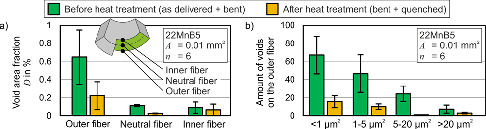 |
| Fig. 10: Void analysis on bent specimen before and after heat treatment (quenching): a) void area fraction on outer, neutral and inner fiber, b) amount of voids on outer fiber in order of their size |
Summary and conclusion
In the 1st funding period, the hypothesis that damage during sheet metal bending can be controlled by lowering the triaxiality was proven, and it was demonstrated that damage significantly influences product performance. In the 2nd funding period it was shown that void shrinkage is possible due to changes of loading direction for DP800. However, it is not clear under which conditions shrinked and/or closed voids grow again when subsequent loading is applied, and if these results can be transferred to other material classes. From hot stamping investigations it was identified, that heat treatment is a viable option for reducing void area fractions, although the exact mechanisms involved are not yet fully understood. In addition to addressing the new phenomenon of void closure, it is essential to consider cyclic loading for accurate predictions of component performance even in complex, multi-stage forming operations that potentially involve heat treatments.
Project- and subject-related list of publications
| [Den18] | Deng, N., Kuwabara, T., Korkolis, Y.P., 2018. On the non-linear unloading behavior of a biaxially loaded dual-phase steel sheet. International Journal of Mechanical Sciences. 138-139, pp. 383–397. doi: 10.1016/j.ijmecsci.2018.02.015. |
| [Kon22] | Kong, X., Helfen, L., Hurst, M., Hänschke, D., Missoum-Benziane, D., Besson, J., Baumbach, T., Morgeneyer, T.F., 2022. 3D in situ study of damage during a ‘shear to tension’ load path change in an aluminium alloy. Acta Materialia 231 (117842). |
| [Lem90] | Lemaitre, J., Chaboche, J.-L., 1990. Mechanics of Solid Materials, Cambridge University Press. ISBN: 9781139167970. doi: 10.1017/CBO9781139167970 |
| [*Len23a] | Lennemann, P., Grodotzki, J., Tekkaya, A.E., 2023. Controlling the Damage Evolution in Roll Forming of a V-Section by Elastomer Rollers. Proceedings of the 14th International Conference on the Technology of Plasticity - Current Trends in the Technology of Plasticity. ICTP 2023. Lecture Notes in Mechanical Engineering. Springer, Cham. doi: 10.1007/978-3-031-42093-1_26 |
| [*Len23b] |
Lennemann, P., Grodotzki, J., Tekkaya, A. E., 2023. Damage in sheet-metal forming under changing strain paths. submitted (AIME) |
| [Med20] | Medghalchi, S., Kusche, C.F, Karimi, E., Kerzel, U., Korte-Kerzel, S., 2020. Damage Analysis in Dual-Phase Steel Using Deep Learning: Transfer from Uniaxial to Biaxial Straining Conditions by Image Data Augmentation. The Journal of The Minerals, Metals & Materials Society (TMS), vol. 72. doi: 10.1007/s11837-020-04404-0. |
| [*Mey19a] | Meya, R., Kusche, C., Löbbe, C., Al-Samman, T., Korte-Kerzel, S., Tekkaya, A., 2019. Global and High-Resolution Damage Quantification in Dual-Phase Steel Bending Samples with Varying Stress States. Metals, vol. 9, 319. doi: 10.3390/met9030319. |
| [*Mey19b] | Meya, R., Löbbe, C., Tekkaya, A. E., 2019. Stress state control by a novel bending process and its effect on damage evolution and product performance. International Journal of Manufacturing Science and Engineering 141 (10), pp. 101013-1-8. doi: 10.1115/1.4044394 |
| [*Mey21] | Meya, R., Lennemann, L., Rethmann, P., Tekkaya, A. E., 2021. Analyse und Kontrolle der Schädi-gungsentwicklung beim Biegen von hochfesten Werkstoffen. In: Tagungsband Ilmenauer Federntag. Ilmenau: Verlag ISLE, ISBN: 978-3-948595-05-0, 2021. |
| [Mil19] |
Milkereit, B., Starink, M.J., Rometsch, P.A., Schick, C., Kessler, O., 2019. Review of the Quench Sensitivity of Aluminium Alloys: Analysis of the Kinetics and Nature of Quench-Induced Precipitation. Materials 2019, 12(24), 4083, doi: 10.3390/ma12244083 |
| [Pue20] | Pütz, F., Henrich, M., Roth, A., Könemann, M., Münstermann, S., 2020. Reconstruction of Micro-structural and Morphological Parameters for RVE Simulations with Machine Learning. Procedia Manufacturing, vol. 47, 629–635. doi: 10.1016/j.promfg.2020.04.193. |
| [Sch85] | Schmitt, J.H, Aernoudt, E., Baudelet, B., 1985. Yield loci for polycrystalline metals without texture. Materials Science and Engineering, vol. 75. doi: 10.1016/0025-5416(85)90173-9. |
| [Spr20] | Sprave, L., Menzel, A., 2020. A large strain-gradient-enhanced ductile damage model – Finite ele-ment formulation, experiment and parameter identification. Acta Mechanica, 231(12), 5159–5192, doi: 10.1007/s00707-020-02786-5 |